Документация про дисковод Gotek на Орион-128, пишем на флэшку
Как использовать флэшки в качестве НГМД, работа в CP/M-80 и в DS DOS
Продаю платы и наборы микросхем, куплю микросхемы Заказать запчасти на ПК Орион-128
11/12/2021, наконец методом "научного тыка" разобрались с Готеком.
Программа редактирования образов дискет на флэшке Готека
Прошивка "Готека", как прошивать "Готек", установка энкодера и LED индикатора


Распиновка разьемов 34 пин на дисководах
Готек прекрасно влился в Орион-128 и Орион Про, без него работа была бы кошмарной. Все хранится на флэшке. Одних дисководов 3,5 и 5,25 для работы с дисками недостаточно!!
Для комфортной работы 2ва устройства (либо 2 готека, либо готек + любой дисковод)
Готек купленый на Али, требует перепрошивки и некоторых модификаций. У одного и того же продавца с разницей год пришли разные готеки (разные платы и чипы)
И так приступаем, но поясняю, документация не проверенная взятая с инета:
Если вы предварительно запрограммировали полную прошивку, вы можете делать будущие обновления через USB-накопитель.
Когда вам будет предложено нажать обе кнопки, нажмите Prev и Next. В качестве альтернативы вы можете нажать «Выбрать» или «Вращающийся кодер», если они у вас есть.
- Удалите все старые файлы * .upd из корня USB-накопителя.
- Скопируйте файл * .upd из корня архива выпуска в корень USB-накопителя.
- Вставьте USB-накопитель в Gotek и включите его при нажатии обеих кнопок.
- Теперь вы должны быть в загрузчике («UPD»). Отпустите обе кнопки.
- Последняя прошивка будет запрограммирована, и Gotek перезагрузится.
- Успех!
На светодиодном дисплее отображаются ошибки во время обновления:
- E01 Файл с исправлением не найден
- E02 Найдено несколько файлов обновлений
- Недопустимый файл обновления E03 (плохая подпись или размер)
- Файл обновления E04 поврежден (плохой CRC)
- E05 Ошибка программирования Flash
- Ошибка Fxx FatFS (возможно, плохой USB-накопитель или файловая система)
Обновление загрузчика
Основной загрузчик также может быть обновлен USB-накопителем. Обратите внимание, что для успешной операции важно, иначе Gotek потребует полного повторения . Поэтому убедитесь, что у Gotek есть стабильный источник питания и известный USB-накопитель.
Новые функции и исправления редко встречаются. В общем случае вам не нужно обновлять загрузчик и пропустить эти шаги.
Повторяю: не следуйте этим шагам, если вы не уверены в том, что делаете.
Когда вам будет предложено нажать обе кнопки, нажмите Prev и Next. В качестве альтернативы вы можете нажать «Выбрать» или «Вращающийся кодер», если они у вас есть.
-
Запрограммируйте «Reloader»
- Удалите все старые файлы * .upd и * .rld с USB-накопителя.
- Скопируйте содержимое перегружателя / папки выпуска в корень USB-накопителя.
- Вставьте USB-накопитель в Gotek и включите его при помощи обеих кнопок.
- Теперь вы должны быть в загрузчике («UPD»). Отпустите обе кнопки.
- «Перегрузчик» будет запрограммирован, и Gotek перезагрузится.
-
Запрограммируйте последний загрузчик
- Теперь вы должны быть в перезагрузке («RLD»). Нажмите и отпустите обе кнопки.
- Будет запрограммирован последний загрузчик. Затем Gotek перезагрузится.
-
Запрограммируйте последнюю главную прошивку
- Вы снова находитесь в перезагрузке. Выключение.
- Удалите файлы * .upd и * .rld с USB-накопителя.
- Скопируйте файл * .upd из корня архива выпуска на USB-накопитель.
- Вставьте USB-накопитель в Gotek и включите его при помощи обеих кнопок.
- Теперь вы должны быть в загрузчике («UPD»). Отпустите обе кнопки.
- Последняя прошивка будет запрограммирована, и Gotek перезагрузится.
- Успех!
Помимо этого: что делают эти шаги
Некоторые люди путаются с приведенной выше последовательностью шагов, и это может помочь дать им ментальную модель того, что происходит. Во-первых, убедитесь, что флэш-память содержит две программы: загрузчик и главную прошивку . Единственная цель Bootloader - разрешить обновление основной прошивки. Конечно, основная прошивка запускает эмуляцию флоппи-дисковода и не знает, как обновлять что-либо. Фокус в обновлении загрузчика заключается в замене основной прошивки на альтернативную программу ( Reloader ), единственной целью которой является обновление загрузчика.
Основная последовательность шагов по обновлению загрузчика:
- Старый загрузчик перезаписывает старую основную прошивку с помощью Reloader
- Reloader перезаписывает старый загрузчик с новым загрузчиком
- Новый загрузчик перезаписывает перезагрузку с помощью новой главной прошивки
*********************

Звук в Готеке подключаем пищалку, имитация звука дисковода в Орионе, все видно из схемы, транзистор кт3102, резистор 1ком.
Но у меня пищалка подключена напрямую. Кроме того в файле конфигурации FF.CFG на флэшке можно менять громкость звука.
И так о самом готеке, информация на английском, кто захочет переведет
Hardware Mods · keirf/FlashFloppy Wiki · GitHub последние доработки https://github.com/keirf/FlashFloppy/wiki/Hardware-Mods
Board Layout
Most modifications simply involve plugging new hardware add-ons into pin headers on the Gotek PCB. The PCB layout is summarised below. We will refer to this diagram for each hardware mod.

Speaker
A speaker can be attached to the Gotek to sound whenever the drive heads move. The simplest method is to connect a piezo sounder directly to the JB header pins.

There is also a step-by-step video describing this mod:

If you want to connect a magnetic speaker instead, you must buffer via an NPN transistor. If you don't know what this means just be sure to use a piezo sounder, easily found on Ebay, and connect it directly as shown above.
Eject/Select Button
FlashFloppy supports a third button in addition to the basic up/down controls. This should be a standard momentary microswitch, connected to the header pins JA.
The button's effect depends on the current state of operation:
- When an image is loaded, the button will immediately eject it
- When selecting an image, the button will immediately confirm the currently-selected image
LCD Display
As an alternative to the Gotek 7-segment display, FlashFloppy supports the ubiquitous 1602 LCD with I2C backpack board. These are available from many Ebay sellers.
You can locate the required connections on your Gotek PCB as below. These connect to the corresponding header pins on your LCD I2C backpack module.
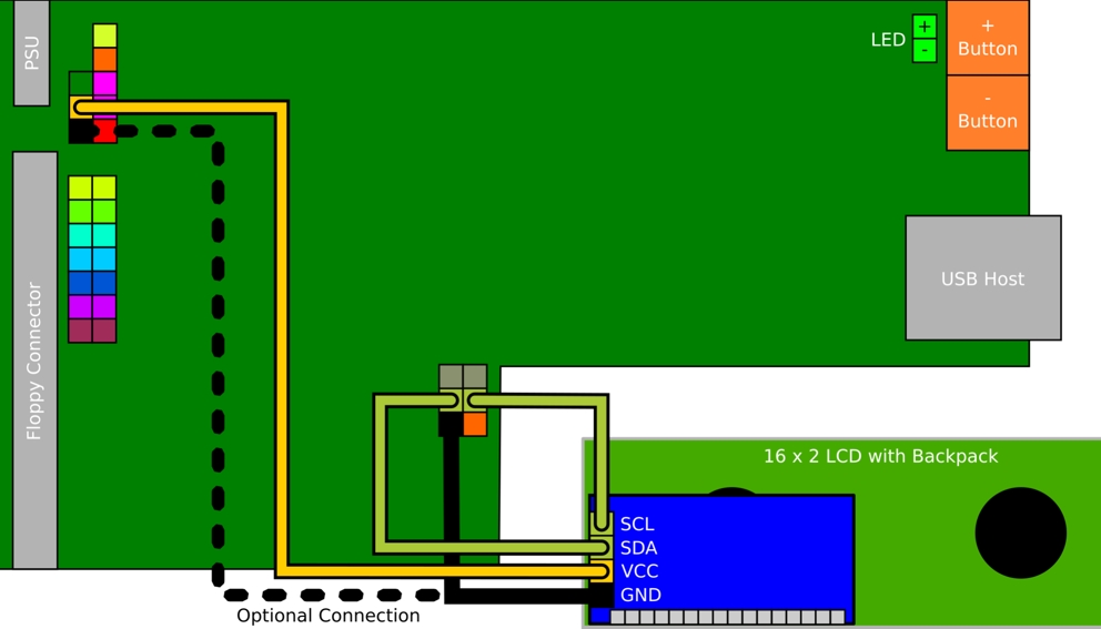
The SCL and SDA lines must be connected to VCC ("pulled up" to VCC) via 4.7k resistors. Note that many I2C boards have the pullup resistors on board and in this case you do not need to attach your own external pullups. You can confirm this by checking the resistance between SDA/SCL and VCC. If it is less than 10k you do not need to add pullups.
If you do require the pullup resistors, these can be soldered to the backside of the Gotek PCB between VCC and each of SDA and SCL. Alternatively the resistors can be soldered to the back of the I2C module header.

OLED Display
Another alternative to the Gotek 7-segment display is a 0.91" 128x32 display, as sold for Arduino projects by many Ebay sellers. You will require a display with I2C interface: you should see it has a 4-pin header marked GND, VCC, SCL, SDA.
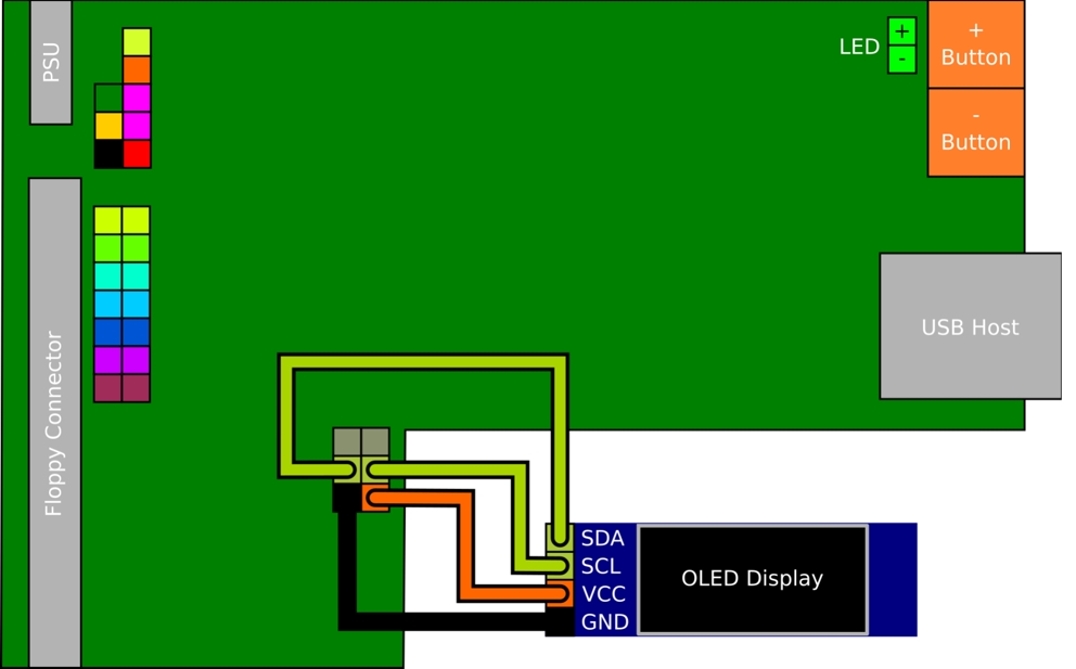
These displays can simply connect to the 7-segment display's header, reusing the existing jumper wires.

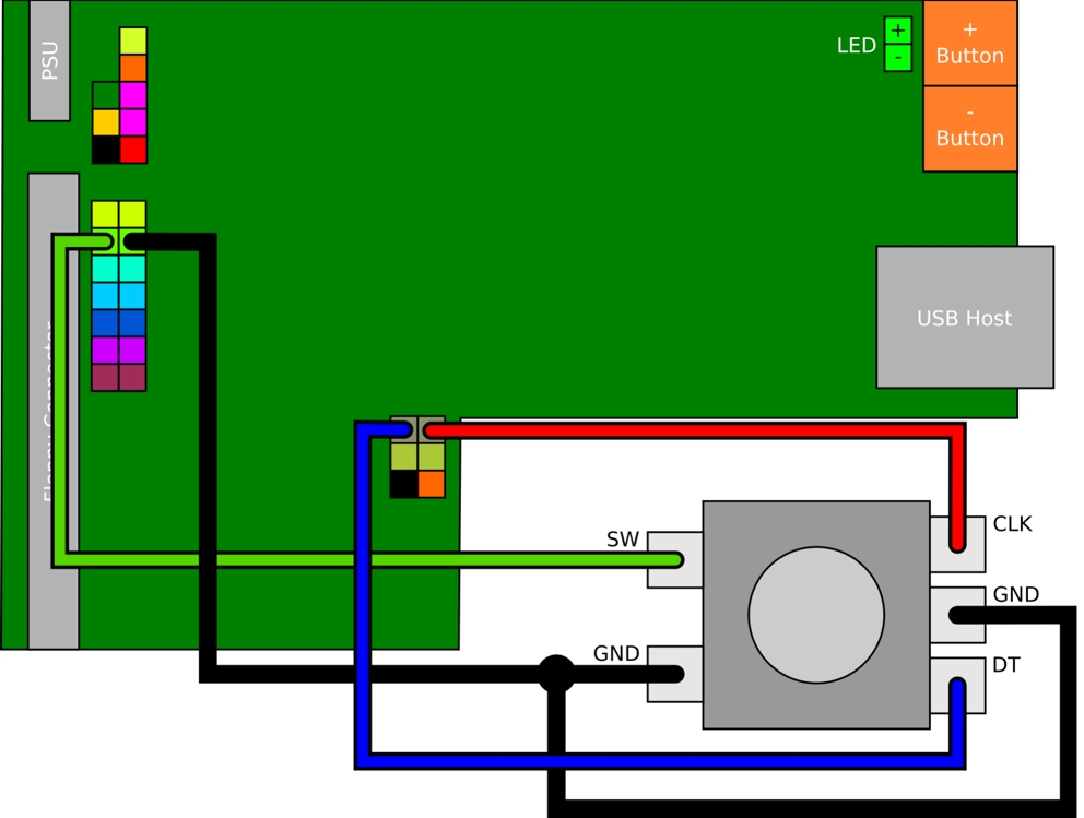
Rotary Encoder
As an alternative to using the up/down buttons you can instead connect a rotary encoder. The pictures below show how to connect it, either directly or via a PCB module (eg KY040).
When connecting via a PCB module, you may need to connect to 3.3v if the board has pull-up resistors mounted.

If connecting directly note that by convention GND is always the middle pin in the row of three. If there is a further row of two pins then these are connected to an internal push switch: you can wire these pins to jumper JA to use the switch as an eject/select button. Ссылка https://github.com/keirf/FlashFloppy/wiki/Hardware-Mods#ejectselect-button
Rotating the dial should now have the same effect as pushing the buttons: anti-clockwise for down, and clockwise for up.
Troubleshooting:
- Directional controls are inverted: swap the A and B (aka CLK, DT) wires.
-
Four clicks
are required to move a single step: specify
rotary=grayin FF.CFG -
PCB modules
only: Both directions move up (or down):
- Connect + to 3.3V (marked in picture above); or
- Remove pull-up resistors from the back of the PCB; or
- Remove the encoder from the PCB and solder wires directly.
!!!!!!!!!!! Troubleshooting:
- SFRC922AT3: This PCB is missing the CLK/DT header. Instead the CLK/DT wires can be connected to pins PA13 (SWDIO) and PA14 (SWCLK) on the programming port. Ссылка https://raw.githubusercontent.com/wiki/keirf/FlashFloppy/assets/pheader.jpg
- SFRKC30.AT2,AT3,AT4: These models have an alternative header for connecting the rotary encoder. See below. Ссылка https://github.com/keirf/FlashFloppy/wiki/Hardware-Mods#kc30-rotary-header
- Directional controls are inverted: swap the A and B (aka CLK, DT) wires.
-
Four clicks are required to move a single step: specify
rotary=grayin FF.CFG - ссылка https://github.com/keirf/FlashFloppy/wiki/FF.CFG-Configuration-File -
PCB modules only: Both directions move up (or down):
- Connect + to 3.3V (marked in picture above); or
- Remove pull-up resistors from the back of the PCB; or
- Remove the encoder from the PCB and solder wires directly.
Enhanced Gotek
Gotek clone designers can choose to add various enhancements to the standard Gotek, all supported by the FlashFloppy firmware. Note that these instructions are intended for PCB designers and cannot be retrofitted to a standard Gotek without fine soldering skills. Regular Gotek users should therefore skip this section.
Summary
- PC12-15: Board Identifier
- PA3: Second Drive Select
- PA15: Motor-On Signal
- PA4-5: USB Power Switch
Board Identifier
Pins PC12-15 are used to identify an enhanced Gotek. On a standard Gotek board these pins are disconnected and floating. On an enhanced Gotek they should all be connected to VSS (GND).
On an enhanced Gotek PC12-15 are selectively connected to VSS (GND). The four inputs PC[15:12] form a four-bit board identifier:
- 0000: Enhanced Gotek, no SD card connector
- 0001: Enhanced Gotek, with SD card connector
- 1111: Standard Gotek (no enhancements)
Second Drive Select
FlashFloppy may in future emulate two drives in a single Gotek. To support this pin PA3 may be connected to a second drive-select line and pulled up by 1K to VCC (5v). If second-drive select is not supported then the pull-up is still required, to avoid PA3 floating.
Motor-On Signal
FlashFloppy may in future use the motor-on signal to improve emulation accuracy. To support this pin PA15 may be connected to the motor-on line (eg floppy pin 16) and pulled up by 1K to VCC (5v). If the motor-on signal is not supported then the pull-up is still required, to avoid PA15 floating.
USB Power Switch
A power switch with active-low enable and open-drain fault output may be connected as follows:
- PA4: active-low enable (output to USB power switch)
- PA5: open-drain active-low fault signal (input from USB power switch)
These connections are optional and either pin may instead be left disconnected and floating (the STM32 will pull them to a defined level).
A suitable power switch is STMicroelectronics STMPS2141.
SD Card Connector (от прошивки v.015)
An SD card connector may be connected as follows:
- PB12: SPI_CS (Chip Select)
- PB13: SPI_CK (Clock)
- PB14: SPI_MISO
- PB15: SPI_MOSI
- PC9: Card Detect
Card Detect should float when a card is inserted, and be driven low when no card is present. For simplest connection, this will require a card-detection switch which is open when a card is inserted, and closed when ejected. A switch with the opposite sense will require extra circuitry (eg. pull-up resistor and an open-drain MOSFET to invert the switch signal).
*******************
By default FlashFloppy will emulate the Shugart floppy interface. This is compatible with a broad range of systems including Amiga, Atari ST, Amstrad CPC, and many other devices. Shugart-compatible systems will typically expect the Gotek to respond as 'unit 0'. Therefore place the selection jumper at location S0 at the rear of the Gotek. IBM PC compatibles use a slightly modified interface which places the disk-changed signal on a different pin. To select this interface mode place a jumper at location JC at the rear of the Gotek. The host system may expect the Gotek to respond as 'unit 1': in this case place the selection jumper at location S1 at the rear of the Gotek. An alternative method to specify the interface mode (Shugart or PC) is via the FF.CFG file, described below.FF.CFG Configuration File
Defaults
Out of the box, FlashFloppy loads the default values described in the Options list, below. When these are modified by values in FF.CFG they are recorded into the Gotek's Flash memory and become the new default values when the drive is next powered on. If you wish to return to 'factory defaults', press the Prev and Next buttons (or Select, or the rotary encoder, if you have them) for three seconds with no USB stick inserted. The display will show "RST" or "Reset Flash Configuration", and FlashFloppy will return to factory defaults when the buttons are released.Options
Default values are marked by asterisk.
Drive Emulation:
· interface = shugart | ibmpc | ibmpc-hdout | akai-s950 | amiga | jc*
- Pin assignments of the floppy-drive interface
- shugart: Shugart interface (Amiga, Atari ST, many others)
- ibmpc: IBM PC interface, no connection on pin 2
-
ibmpc-hdout:
IBM PC, high-density-select output (Gotek->host) on pin 2
- Do not select this option unless explicitly required for your system!
- It is not required for IBM PC compatibles. Use ibmpc instead.
- akai-s950: Akai S950
-
amiga:
Drive ID hack on pin 34. Use shugart instead
when possible.
- See Amiga-specific for advice on this setting.
- jc: Specified by jumper JC (closed = IBM PC, open = Shugart)
· host = unspecified* | acorn | akai | ...
- Host platform: Improves image-format detection for generic types such as IMG and DSK
- acorn: Acorn ADFS
- akai: Akai synths (S01, S20, S950)
- dec: DEC (RX33, RX50)
- ensoniq: Ensoniq synths (ASR/TS series, and others)
- fluke: Fluke (9100)
- gem: General Music (S2, S3, S2R)
- kaypro: Kaypro
- memotech: Memotech
- msx: MSX
- nascom: Nascom (1, 2)
- pc98: NEC PC-98
- pc-dos: PC DOS Format (geometry determined from Bios Parameter Block)
- tandy-coco: Tandy Color Computer (CoCo)
- ti99: TI-99/4A
- uknc: UKNC, DVK (Soviet PDP-11)
- unspecified: Detection based on image-name suffix only
· pin02 = auto* | nc | low | high | rdy | nrdy | dens | ndens | chg | nchg
- Manually assign an output signal (Gotek->host) to floppy interface pin 2
- auto: Automatically determined from interface = setting
- nc: Unused / No Connection
- low, high: Constant low (0v) or high (5v) voltage
- rdy, nrdy: Drive ready, or logical complement
- dens, ndens: Density mode (HD = 0v), or logical complement
- chg, nchg: Disk changed, or logical complement
· pin34 = auto* | nc | low | high | rdy | nrdy | dens | ndens | chg | nchg
- Manually assign an output signal (Gotek->host) to floppy interface pin 34
· write-protect = yes | no*
-
Are
images write protected when initially mounted?
- Protection can be toggled by holding eject for 2 seconds
- yes: Forcibly write-protect images
- no: Respect the FAT read-only attribute
· side-select-glitch-filter = 0-255 (0*)
- Filter glitches in the SIDE-select signal shorter than N microseconds
- Useful on some old hardware (eg. CP/M systems)
· track-change = instant* | realtime
- Rotational offset of data after a track change
- instant: No rotation during track change
- realtime: Emulate rotation of disk while track is changing
· index-suppression = yes* | no
- Are index pulses suppressed when RDATA and WDATA inactive?
- Older systems may depend on constant index pulses (eg. BBC Micro)
· head-settle-ms = 0-255 (12*)
- Milliseconds from head-step start to RDATA active
Startup & Initialisation:
· ejected-on-startup = yes | no*
- Disk image loaded or ejected at power on
· image-on-startup = last* | static | init
- Which image (or folder) is selected at startup
- last: Last-selected item at power off (recorded in IMAGE_A.CFG)
- static: Static pathname specified in IMAGE_A.CFG
- init: First item in root folder
· display-probe-ms = 0-65535 (2000*)
- Time in milliseconds to attempt to probe an attached display
- If you have a 2-digit LED display, or no display: Set to 0 for faster startup
Image Navigation:
· autoselect-file-secs = 0-255 (2*)
- Auto-select the current file/slot after N seconds
- N=0: disable auto-select
· autoselect-folder-secs = 0-255 (2*)
- Auto-select the current folder after N seconds
- N=0: disable auto-select
· nav-mode = native | indexed | default*
- Navigation mode for selecting images or slots
- native: Navigate through all valid images and folders
- indexed: Navigate through DSKA0000, DSKA0001, ...
- default: As native unless overridden by HxC-compat-mode config
· nav-loop = yes* | no
- When navigating slots or a folder, loop at start/end of the list
· twobutton-action = zero* | eject | rotary | rotary-fast | reverse
- Actions of first two buttons
- Multiple values can be specified, separated by commas (eg. rotary,reverse)
- zero: 1: Prev, 2: Next, Both: Slot 0
- eject: 1: Prev, 2: Next, Both: Eject/Insert
- rotary: 1: Up-dir, 2: Select/Eject/Insert, Both: -
- rotary-fast: 1: Prev (accelerated), 2: Next (accelerated), Both: Up-dir
- reverse: Reverse operation of the buttons (useful if installed upside down)
· rotary = none | quarter | half | full* | reverse
- Type of rotary encoder connected to pins PC10 and PC11
- Multiple values can be specified, separated by commas (eg. half,reverse)
- none: No rotary encoder is connected
-
quarter, half, full:
Fraction of a Gray-code cycle performed per detent/click
- Select half if default value (full) requires 2 clicks per move
- Select quarter if default value (full) requires 4 clicks per move
- reverse: Reverse direction of the knob (useful if wired backwards!)
Display:
· display-type = auto* | lcd-NNx02 | oled[-128xNN][-rotate][-narrow][-sh1106]
- auto: Auto-detect (7-seg LED, LCD, OLED)
- lcd-NNx02: NNx2 backlit LCD with I2C backpack (16 <= NN <= 40)
-
oled-128xNN:
128xNN I2C OLED (NN = 32 | 64)
- -rotate: OLED view is rotated 180 degrees
- -narrow: OLED view is restricted to Gotek display cutout
- -sh1106: SH1106 controller (default is SSD1306)
· oled-font = 6x13* | 8x16
- Select 6px- or 8px-wide OLED display font
-
6x13 font permits:
- More characters per row
- Use of Gotek display cutout (with display-type=oled-128x32-narrow)
· oled-contrast = 0-255 (143*)
- OLED contrast/brightness
· display-off-secs = 0-255 (60*)
- Turn LCD/OLED display off after N seconds of inactivity
- N=0: always off
- N=255: always on
· display-on-activity = yes* | no
- Automatically switch LCD/OLED display on when there is drive activity
· display-scroll-rate = 100-65535 (200*)
- LCD/OLED long filename scroll rate (ms per update)
- Larger value means slower scroll
· display-scroll-pause = 0-65535 (2000*)
- LCD/OLED long filename scroll start/end pause (ms)
- N=0: Endless looping scroll
· nav-scroll-rate = 0-65535 (80*)
- LCD/OLED long filename scroll rate during navigation (ms per update)
· nav-scroll-pause = 0-65535 (300*)
- LCD/OLED long filename pause before scroll starts during navigation (ms)
Miscellaneous:
· step-volume = 0-20 (10*)
- Speaker volume (connected at jumper JB) when drive heads are moved
· da-report-version = quoted-string
- Report the specified version number to host software
- Empty string ("") means report the firmware version number
- For example: da-report-version = "v3.0.0.0"
· extend-image = yes* | no
-
Automatically extend a truncated image file at mount/insert time
- Applies to SSD, DSD, TRD images only
**************************
Most systems require Shugart interface (the default) and select line 0 (jumper on S0). Such systems will work out of the box with a factory-fresh Gotek programmed with FlashFloppy firmware, requiring only a physical jumper at the rear to be moved from S1 to S0. If this does not work then also try the following:- Jumper at S1 only
- Jumpers at JC and S0
- Jumpers at JC and S1
Acorn Archimedes
Acorn BBC Micro
Akai Synthesisers
Amstrad CPC
Physical Connection of a Standard Gotek
See here (ссылка http://www.cpcwiki.eu/index.php/DIY:Floppy_Drives) for guidance on connecting the CPC's 26-pin cable to the Gotek 34-pin header. Also note that the CPC's power cable has +5v and +12v reversed: you must use an adapter or otherwise somehow insert the power connector backwards. If you do not, you will damage your Gotek and destroy any USB stick that you insert! Note that Gotek clones designed specifically for CPC (or Spectrum +3) will use the data and power connectors as-is, and the above should be ignored.Amstrad PCW
Fixing Boot-Time Hangs
Later versions of LocoScript and CP/M require Drive A to correctly respond to the Motor signal (Gotek pin 16), by deasserting Ready (Gotek pin 34) when the motor is off. Unfortunately the Gotek usually ignores Motor, and the PCW will hang during boot waiting for the drive to respond correctly. This page (ссылка https://fabriziodivittorio.blogspot.com/2018/05/installazione-gotek-su-amstrad-pcw-9512.html) (in Italian, so use Google Translate) explains how to modify the Gotek to fix this problem. Section 8.3 of this document (ссылка https://www.seasip.info/Unix/Joyce/hardware.pdf) gives more technical information on the floppy-drive probe logic which causes this issue.Atari ST
Commodore Amiga
Internal Drive (DF0)
To replace an existing Amiga internal drive usually requires a jumper on S0 only. One exception are Escom A1200 boards, which are modded to use PC drives: if you have one of these then you require a jumper on JC (or interface = ibmpc in FF.CFG). For improved compatibility you can undo the Escom mod as described by RetroGameModz. (ссылка https://www.youtube.com/watch?v=G6fYOjTYvXM)External Drive (DF1-DF3)
Replacing an external drive depends on the enclosure or cable being used. Amiga external drive enclosures usually include the circuitry to allow the Amiga to identify the presence of the drive. In this case the Gotek with S0 jumper is usually a straight swap for the old floppy drive. If using a passive cable such as this Ebay item (ссылка https://www.ebay.co.uk/itm/272363110859) then be aware that this identification circuitry is missing, but for arcane reasons identification will typically happen to work as long as the Gotek has an image mounted when the Amiga boots. If you are having problems with your drive being identified, see Forcing Drive (ссылка https://github.com/keirf/FlashFloppy/wiki/Host-Platforms#forcing-drive-identification) Identification below.High-Density Disks
Amiga Kickstart versions 2.05 and later support high-density disks with 1760kB formatted capacity. This enhancement required a customised (and nowadays expensive!) HD drive modified to rotate at half speed and emit a special ID sequence to the Amiga when an HD disk is inserted. FlashFloppy supports this enhancement for 1760kB ADF images, but the high-density ID sequence must be explicitly enabled in FF.CFG. (ссылка https://github.com/keirf/FlashFloppy/wiki/Host-Platforms#forcing-drive-identification) If using an Amiga external drive enclosure, please bear in mind that the enclosure's interface board usually emits a fixed double-density ID sequence which will make HD images unreadable. In this case you must disconnect the enclosure's ID circuitry on its interface PCB:- Cut the PCB connection to external connector, pin 1.
- Connect a jumper wire between internal connector pin 34 and external connector, pin 1.
Forcing Drive Identification
Amiga hosts expect a drive ID sequence from external and Amiga-high-density drives on pin 34 of the floppy interface when the drive motor is disabled (pin 34 carries the Ready/RDY signal when the drive motor is enabled). In contrast, FlashFloppy's default interface mode (interface = shugart) permanently attaches RDY to pin 34, regardless of motor. This default behaviour usually works fine:- Drive ID signalling is not a strict requirement for DF0
- External drive enclosures often implement the drive-ID circuitry
- A mounted disk image asserts RDY which happens to match the Amiga ID sequence for a DD drive anyway
- Using high-density disk images (1760kB formatted capacity)
- Using as an external drive with a passive interface cable, if FlashFloppy does not assert RDY during boot (eg. eject-at-power-on, no USB stick, or too slow to initialise)
DEC
Dragon
E-mu ESI-32
Ensoniq
- host = ensoniq is required in FF.CFG for IMG-format support
- IMG format is not supported for Mirage or SQ-80 (ie. 880kB) formats
- IMG format is especially preferred for 1600kB HD disks
General Music (GEM) Synthesisers
IBM PC
-
IBM-PC interface mode must be configured
- Strap jumper JC at the rear of the Gotek; or
- Specify via FF.CFG: interface = ibmpc
-
Strap select-line jumper S1 at the rear of the Gotek
- S0, S2, MO should all be left open
- Amstrad PPC512, PPC640
Korg
Memotech
MSX
NEC PC-98
Roland
Sequential Circuits Prophet 3000
Spectrum
- Using Simon Owen's SAMdisk (ссылка http://simonowen.com/samdisk)
- Using the Python script included in the FlashFloppy distribution
Spectrum +3: Physical Connection of a Standard Gotek
See here (ссылка http://www.cpcwiki.eu/index.php/DIY:Floppy_Drives) for guidance on connecting the Spectrum +3's 26-pin cable to the Gotek 34-pin header. Also note that the +3's power cable has +5v and +12v reversed: you must use an adapter or otherwise somehow insert the power connector backwards. If you do not, you will damage your Gotek and destroy any USB stick that you insert! Note that Gotek clones designed specifically for CPC and Spectrum +3 will use the data and power connectors as-is, and the above should be ignored.Tandy Color Computer
TI-99/4A
UKNC, DVK
These Soviet PDP-11 clones have a modified IBM track format which must be explicitly configured via host = uknc in FF.CFG.
****************************
Error Messages
When an unrecoverable error occurs a message will be displayed on the LED, LCD, or OLED screen. F-F / FlashFloppy vx.y This is not explicitly an error code or condition, but the default display if a valid USB stick is not inserted. Make sure your USB stick is properly inserted, legacy partitioned (MBR rather than GPT) and FAT32 formatted. Fnn / *FAT*nn* / *FATFS* nn A 2-digit error code defined by the FatFS library. In HxC Compatibility mode this probably means you have stale slot assignments in HXCSDFE.CFG. You should copy a fresh version of HXCSDFE.CFG to your USB stick and reassign slots using the Autoboot file selector. In other cases this error usually indicates bad physical media or a bad filesystem. Try formatting or replacing your USB drive. Enn / *ERR*nn* / *ERROR* nn A 2-digit error code defined by the FlashFloppy firmware:- 30 Disk Full: Some writes were lost. Delete some files or use a larger USB drive.
- 31 Bad Image File: The selected image is invalid or unsupported.
- 32 Bad HXCSDFE.CFG: The config file is invalid or unsupported. Copy a fresh version to the USB drive.
- 33 Bad IMAGE_A.CFG: The last-image file has become corrupted. Delete it from the USB drive and it will be automatically recreated.
-
34 No
entries to navigate:
- Direct Navigation mode found no valid directories or image files to display. Add some valid image files to the USB drive. Subfolders are accessible only when using an LCD/OLED display.
- Indexed mode found no valid DSKA*.* image names. Add some valid image files to the USB drive.
- 35 Path too deep: Folders are nested too deeply to navigate.
Over-current condition on the USB port. The port is powered down until a button is pressed.
******************************
Документация про "Готек" предоставленная Владимиром из Сергиева Посада
Купить платы, наборы микросхем на Орион-128 серии 555, кр1533, м533, м531, м530 в дипе, КР565РУ5В, КР565ру7В, к565ру5г AU, к565ру7г Au в позолоте, куплю микросхемы
На предыдущую страницу На главную страницу На следующую страницу